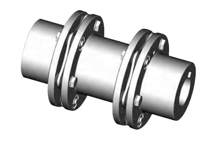
The following data needs to be offered to when placing an order to make  certain the correct collection of the disc coupling:
Application and type of duty
Form of driver (engine, motor, turbine, etc.)
Pace and horsepower
Kind of driven
Shaft sizes and separation
Area limitations for big diameter and length
Style of match (Interference fit default, clearance fit and shaft locking device preparation accessible on request)
Distinctive requirements (vertical mounting, drop out center, flange mount, electrically insulated, API-610 as much as 3,800 RPM, shear pins, balancing, and so forth.)
Angular misalignment, axial misalignment, and rated torque are all related towards the coupling’s capacity to accommodate application torque over any time period of time. As illustrated in the following charts, once the application torque increases to 50% in the coupling capacity, the ability on the coupling to accommodate angular misalignment to is decreased. The same holds correct to the ability to accommodate axial misalignment.
Choice Procedure
one. Select the coupling kind.
two. Select the driven machine support aspect SFA
three. Select the driving machine service component SFD
Care should be taken once the driving machine is apart from a regular electric motor or turbine. Some engines will impose added fluctuations within the drive procedure and allowance ought to be manufactured accordingly. A torsional coupling may perhaps be expected for diesel drives.