The FARR 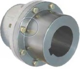 Coupling is utilised when a rigid connection is required in between the reduced pace shaft of the gearbox and the head shaft of a conveyor, bucket elevator, mixer or any over-hung or suspended load. When sized correctly, the FARR Coupling will carry the applica-tion torque, excess weight of gearbox, motor and swing plate. During the situation of a mixer, it’s going to carry the weight in the shaft and impeller, thrust forces and resulting bending moments.
Elements of the FARR Coupling consist of male and female piloted hubs made from 4140 alloy steel. The hubs are extended to assure 80% hub to shaft get in touch with. Keeper plates are included for safety. The two hubs are assembled with Grade eight bolts and Grade À Prevailing Torque nuts. Conventional coupling sizes have a nominal torque vary from eleven,300 to five,736,000 in-lbs. Larger sizes are available based on the application.
Features
Heat Handled 4140 alloy steel
Male and Female pilots
Greater Torque Capability
Grade 8 Bolts / Grade ?¡ãC?¡À Prevailing Torque Nuts
Extended length through bore
Keeper Plate design
FARR Coupling Variety Guide
A. Obtain The following Details:
Application
Horsepower & RPM
Gearbox (Reducer) Ratio
Output Pace
All Shaft Sizes
Overhang Load
Lever Arm
(Distance from end of Gearbox output Shaft to Center-Line of Gearbox or Center Line of Gravity)
B.Calculate Application Torque:
T (in-lb) = ¡ê¡§HP x 63025¡ê?/RPM
C.Calculate Design Torque by applying 2.0 Service Factor to application torque.
D.Select coupling with a torque capacity equal to or greater than the Style and design Torque from the Performance Data table.
E.Verify that the Bore capability from the coupling will meet the application shaft requirements.
F.The Male pilot hub to always be employed to the Reducer (Gearbox or Driver) shaft and also the Female pilot hub to always be utilised around the Head (Driven) shaft.
G.Drive System Analysis must be performed by Application Engineering to verify coupling variety.